
English
- English
- Español
- SaudiArabia
News

What is Optical Fibre Splice Loss?
2026-07-28 23:21:14
Click:
“
What is Optical Fibre Splice Loss?There is no debate that fiber optic cables are
”
What is Optical Fibre Splice Loss?
There is no debate that fiber optic cables are a much swifter, lightweight, flexible, and reliable mode of data transfer over mainstream copper cables. As the demand for data and high-speed communication continues to rise, fiber optic will become ubiquitous.
However, building a long-distance network of optical fiber cable comes with its challenges. Such installation is carried out by joining two fiber ends with a fiber cable connector or a fusion splicer. Naturally, where there is a connection, there will be some form of fiber splicing attenuation i.e., optical signal loss. If designers are not careful, splice loss in optical fiber could be a big hindrance to network performance.
What is Optical Fibre Splicing?
Before we dive headfirst into all sorts of numbers and equations, let us paint a clearer picture of what splicing a fiber optic cable is.
Fiber splicing refers to the process of joining two optical fiber cable to create a longer link for optical signal. Thus, fiber splicing is what makes long-distance optical fiber communication possible. As such, fiber splicing involves couplers to which the end of one fiber bundle and the starting point of another optic fiber bundle are connected. The goal of fiber splicing is to ensure that any light passing through does not get reflected back from the splice point. Thus, adequate splicing can only occur if the two optic fiber bundles align together with proper geometry and strength.
Now, there are two broad fiber splicing types or splicing methods:
- Fusion splicing – You might imagine that fusion fiber splicing indicates fusing together optic fiber cables. That is correct. It is one of the best fiber splicing techniques that can produce a permanent connection. Fusion splicing involves thermally joining optic fiber cable ends using an electric arc. One of the first fusion splicing steps is proper alignment and butting of the two fibers inside a holder. Then, the heat from the electric arc melts the ends of the fiber, fusing them together permanently. A polyethylene jacket covers the burnt area to protect the connetion.
- Mechanical splicing – In mechanical splicing, there are two possible techniques: V-grooved splicing and elastic tube splicing. In the first method, a V-shaped substrate is used to hold the two fibers inside a groove and bond them using an adhesive or index matching gel. In the second method, fibers of different diameters are aligned using symmetrical force inside a rubber elastic material with much smaller hole diameter.
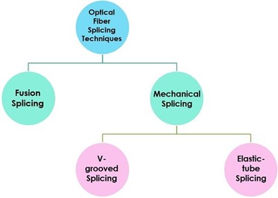
Fusion fiber splicing is the preferred splicing method by designers and installers as it has a low optical loss range between 0.05-0.10 dB. It is also equally efficient for both single mode and multi-mode fibers. On the other hand, mechanical splicing (especially V-groove splicing) experiences greater splice loss due to its non-permanent nature and slight off alignment.
Now, the more the number of splices in an optical fiber connection, the more splice loss. But what exactly is splice loss in optical fiber?
What is Optical Fibre Splice Loss?
As we have already read, an optical fiber beam travelling through the core of an optical fiber cable will gradually lose its signal strength. This phenomenon is called attenuation or fiber optic loss. While there are many ways it could occur, attenuation also happens in the form of optical fiber spice loss.
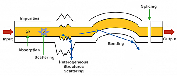
Types of attenuation in an optical fiber cable, including splice loss
Splice loss in optical fiber is defined as the part of optical power that is not transmitted through the splice and is radiated out of the fiber instead. It is measured in decibels (dB) and is given by the formula:
αsplice = 10log10 Pin/Ptrans
Here:
αsplice = Fiber splicing loss
Pin = Total power incident on the fusion splice
Ptrans = Desirable portion of the optical power transmitted across the fusion splice
Given that the total power that a fusion splice receives is always greater than the power it should transmit ideally, splice loss is always in positive. However, in fusion splicing technique, this loss is usually very negligible, often to the tune of 0.05 to 0.1 dB.
The two main reasons why fusion splice loss occurs are due to internal factors, also termed as intrinsic fiber core attenuation, and external factors, also known as extrinsic fiber attenuation. We shall read about these towards the end of the blog. In any case, it is important for manufacturers and optic fiber installers to reduce the splice loss as much as possible. Doing so enables much more effective transmission of the optical signal over longer distances.
How is Optical Fibre Splice Loss Measured?
Now that we know what is fiber splicing and splice loss in optical fiber, are you curious to know how it is measured? The answer is Optical Time Domain Reflectometer (OTDR). It is commonly used to measure fusion splice loss.
The operation of the OTDR is simple. During optical fiber testing, it injects a series of optical pulses into the fiber from one end. Then, it extracts any backscattered light from the same end and measures its strength as a function of both time and the length of the fiber.
Thus, during fusion splicing and measuring with OTDR, when two fibers with different geometric properties and MFD values are spliced, the OTDR captures different volumes of backscattered light. This results in either an apparent gain or loss artifact at the surface. This has been depicted in the illustrations below.
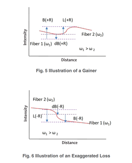
Before the actual splice loss is determined, the error component of the measured splice loss is also determined by the following formula:
αOTDR = 10.log [ω1/ω2]
Here, ω1 and ω2 represent the respective fiber mode-field radius of the first and second fiber.
The total unidirectional OTDR measured splice loss is then calculated using the following equation:
αmeasured = [αothers + αMFD]splice loss + αOTDR
where αmeasured = Unidirectional OTDR loss
αothers = core to core offset, tilt, and other loss mechanisms
αOTDR = Error component of OTDR loss
Now, in order to remove the error component from the splice loss measurement, the OTDR takes a bidirectional reading. In this method, the measurements are taken from both the sides of spliced fibers and consequently measuring the step or gain (A1 and A2) at the splice point. The final splice loss is calculated by taking the average of the bidirectional OTDR traces. This is given by the following formula:
Splice loss = [A1 + A2]/2 = [(Δω + δ) + (-Δω + δ)]/2 = δ
where Δω = αOTDR
δ = [αothers + αMFD]splice loss
Parameters Controlling Optical Fibre Splice Loss
When it comes to splicing fiber optic cable, the splice loss in optical fiber is controlled by two main parameters: intrinsic splice loss and extrinsic splice loss.
- Intrinsic – Fusion splice loss caused due to differences in the optical characteristics of the fibers, such as aperture and core diameter.
- Extrinsic – Fusion splice loss caused due to unevenness of splicing, such as core to core offset, tilt mismanagement and deformation at the splice point.
Intrinsic Parameters
Let us suppose that a set of two single mode fibers are being spliced. Now, since intrinsic parameters deal with loss due to the properties of the fibers themselves, here we can observe that the main difference between the two fibers is their different modal field radius.
To calculate modal field radius, we use the formula:
ω ≈ acore (0.65 + 1.6/v3/2)
where acore = fiber core radius
v = generalised wave number = (2π/λ) acoreNA
Ultimately, the splice loss is a result of the difference in the modal radius of the two fibers at a given wavelength. This loss due to Modal Field Diameter (MFD) mismatch is given by the formula:
αMFD = -20 Log10 [2 ω1ω2/ ω12 + ω22]
The following graph depicts splice loss variation when MFD is kept constant for one fiber and changed for the other. For an MFD difference of 1µm, intrinsic splice loss can reach as high as 0.05 dB.
The second graph, on the other hand, depicts experimentally measured splice loss for G.652.D fibers where one test fiber with a fixed MFD value is spliced to fibers having a range of MFD values
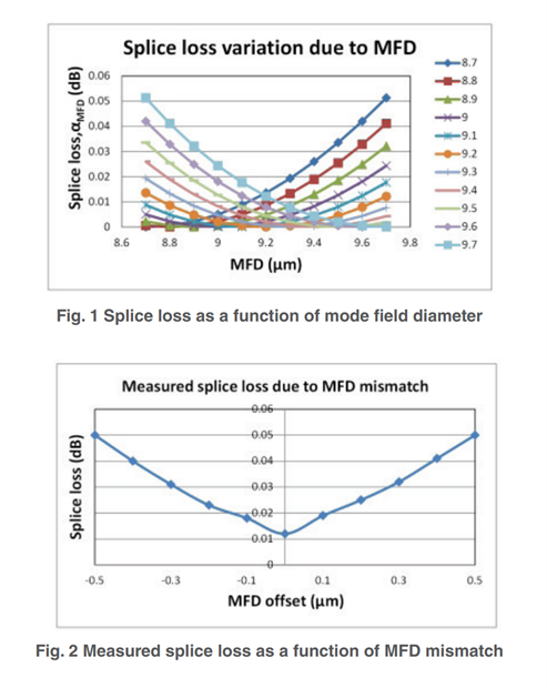
Beyond the usual splice loss, intrinsic attenuation also comprises of absorption losses, dispersion losses and scattering losses.
Extrinsic Parameters
Fiber splicing loss is also dependent upon a host of extrinsic parameters that emerge during the process of splicing. These include:
- lateral and angular alignment
- contamination of fiber ends
- core deformation due to un-optimised heating and pressing
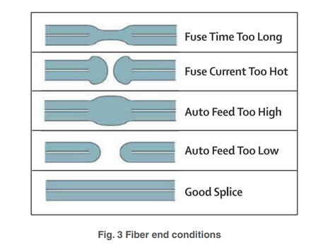
Unoptimised splicing parameters, such as the ones depicted in the below graphic, can induce a splice loss as high as 0.04 dB in two identical fibers. Thus, the importance of using skilled splicing operators and automated equipment cannot be understated.
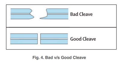
Similarly, in order to get acceptable splice loss, it is important to prepare the fiber end for splicing through a good cleave. Here, it has been found that a cleave angle of less than 2 degrees induces acceptable splice loss.
Beyond fiber splicing loss, other kinds of extrinsic losses include connector loss or insertion loss and bending loss.
Bottom Line
Fiber splicing loss is inevitable – whether intrinsic or extrinsic. However, due diligence must always be done to ensure that it is minimised. That way, the output optical power is well received by the receiver while also leaving a margin of error for any performance degradation over time. Using better quality fiber and advanced splicing technique and skills is paramount.









