
English
- English
- Español
- SaudiArabia
News

What is Fiber Patchcord
2026-07-24 21:02:59
Click:
“
Fiber optic patch cords are used to connect devices to fiber optic cabling links
”
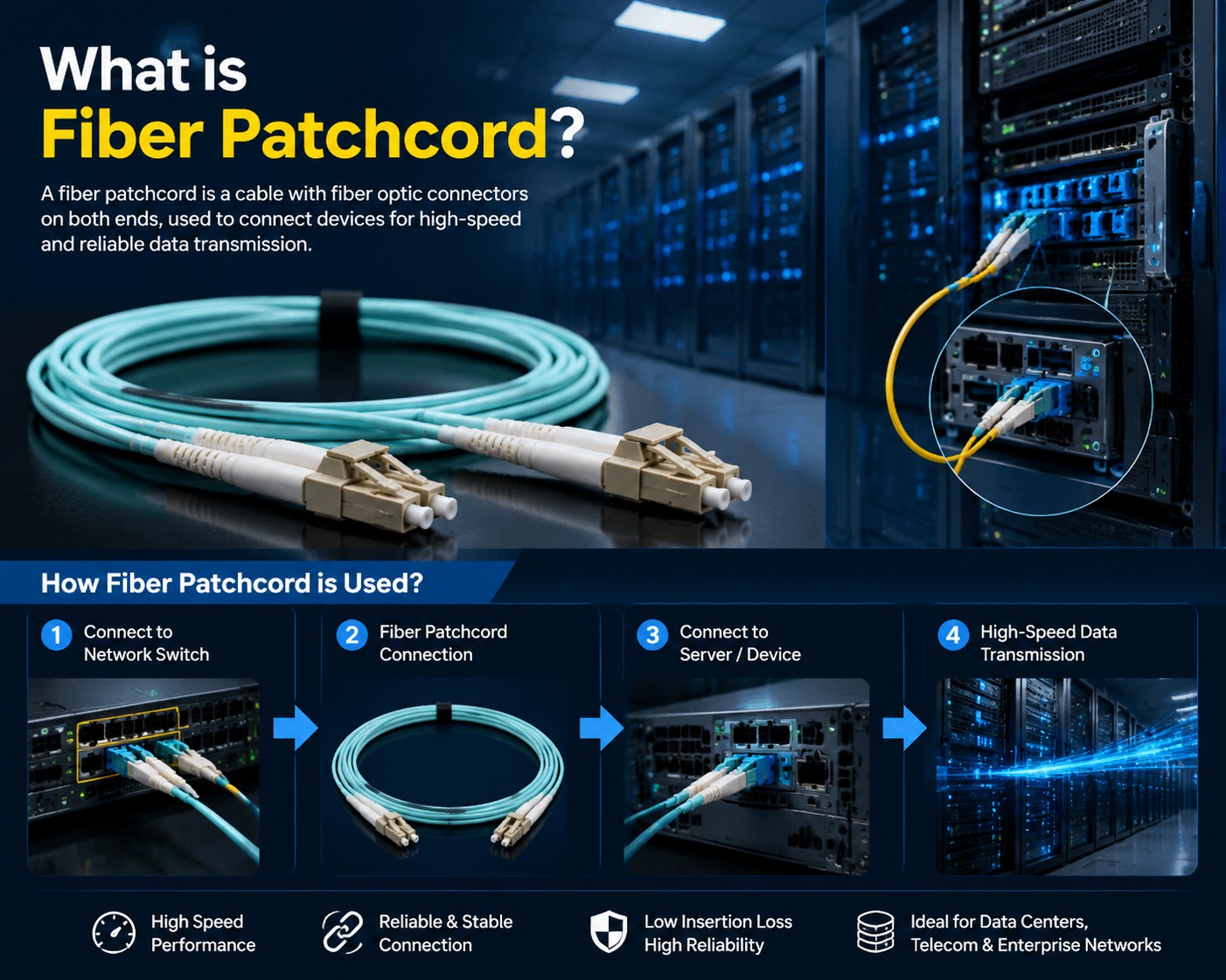
Fiber optic patch cords are used to connect devices to fiber optic cabling links. They have a thick protective layer and are typically used for connections between optical transceivers and terminal boxes, in applications such as fiber optic communication systems, fiber optic access networks, fiber optic data transmission, and local area networks.
Structure:
Fiber optic patch cords (also known as fiber optic connectors) are optical cables with connector plugs at both ends to achieve active optical path connections; those with a plug at only one end are called pigtails. Fiber optic patch cords (Optical Fiber Patch Cords/Cables) are similar to coaxial cables, except they lack a braided shielding layer. The center is a glass core for light propagation. In multimode fiber, the core diameter is 50μm~65μm, roughly the thickness of a human hair. In single-mode fiber, the core diameter is 8μm~10μm. The core is surrounded by a glass cladding with a lower refractive index than the core to keep the fiber within the core. Outside of this is a thin plastic jacket to protect the cladding.
The classification and overview of fiber optic patch cords are as follows:
Fiber optic patch cords(also known as fiber optic connectors) are fiber optic connectors used to connect optical modules. There are several types, and they are not interchangeable. SFP modules use LC fiber optic connectors, while GBIC modules use SC fiber optic connectors. Below is a detailed description of several commonly used fiber optic connectors in network engineering:
1. FC type fiber optic patch cord: External reinforcement uses a metal sleeve, and the fastening method is a screw thread. Generally used on the ODF side (most commonly used on patch panels).
2. SC type fiber optic patch cord: Connector for GBIC optical modules. Its shell is rectangular, and the fastening method is a pull-out latch type, requiring no rotation. (Most commonly used on routers and switches).
3. ST type fiber optic patch cord: Commonly used in fiber optic patch panels. The shell is round, and the fastening method is a screw thread. (For 10Base-F connections, the connector is usually ST type. Commonly used in fiber optic patch panels).
4. LC type fiber optic patch cord: Connector for SFP modules. It uses a convenient modular jack (RJ) latch mechanism. (Commonly used in routers).
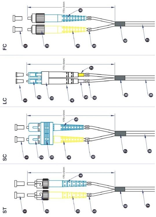
Classification
Fiber optic patch cords can be classified according to their transmission medium into common silicon-based fiber optic single-mode and multi-mode patch cords, as well as others using materials such as plastic. They can also be classified according to their connector structure, including FC, SC, ST, LC, MTRJ, MPO, MU, SMA, FDDI, E2000, DIN4, D4, and many other types. Common types include FC-FC, FC-SC, FC-LC, FC-ST, SC-SC, and SC-ST.
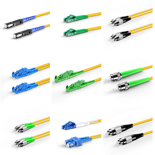
Single-mode fiber optic patch cords are typically yellow, with blue connectors and protective sleeves; they have longer transmission distances.
Multi-mode fiber optic patch cords are typically orange, though some are gray; connectors and protective sleeves are beige or black; they have shorter transmission distances.
Features
1. Low insertion loss;
2. Good repeatability;
3. High return loss;
4. Good inter-insertion performance;
5. Good temperature stability;
6. High tensile strength.
Parameter:
| Item | LC Patchcord | SC patchcord | ST Patchcord | FC Patchcord | MT-RJ | |||||
| single-mode | Multimode | single-mode | Multimode | single-mode | Multimode | single-mode | Multimode | single-mode | Multimode | |
| Insertion loss | ≤0.2dB | ≤0.2dB | ≤0.2dB | ≤0.2dB | ≤0.2dB | ≤0.2dB | ≤0.2dB | ≤0.2dB | ≤0.2dB | ≤0.2dB |
| Return loss | PC≥45 dB UPC≥50 dB APC≥65 dB | PC≥45 dB UPC≥50 dB APC≥65 dB | PC≥45dB UPC≥50d | PC≥45dB UPC≥50dB | PC≥45dB UPC≥50dB | PC≥45 dB | PC≥45dB UPC≥50dB | PC≥45dB UPC≥50dB | PC≥45 dB UPC≥50 dB APC≥65 dB | PC≥45 dB UPC≥50 dB APC≥65 dB |
| Repeatability | ≤0.2dB | ≤0.2dB | ≤0.2dB | ≤0.2dB | ≤0.2dB | ≤0.2dB | ≤0.2dB | ≤0.2dB | ≤0.2dB | ≤0.2dB |
| Interchangeability | ≤0.2dB | ≤0.2dB | ≤0.2dB | ≤0.2dB | ≤0.2dB | ≤0.2dB | ≤0.2dB | ≤0.2dB | ≤0.2dB | ≤0.2dB |
| Temperature range | -40ºC~85 ºC | -40ºC~85 ºC | -40ºC~85 ºC | -40ºC~85 ºC | -40ºC~85 ºC | -40ºC~85 ºC | -40ºC~85 ºC | -40ºC~85 ºC | -40ºC~85 ºC | -40ºC~85 ºC |
Applications:
Fiber optic patch cords are widely used in communication equipment rooms, fiber-to-the-home (FTTH), local area networks (LANs), fiber optic sensors, fiber optic communication systems, fiber optic transmission equipment, and national defense. They are suitable for cable television networks, telecommunications networks, computer fiber optic networks, and optical testing equipment. Specifically, they are used in several areas:
1. Fiber optic communication systems
2. Fiber optic access networks
3. Fiber optic data transmission
4. Fiber optic CATV
5. Local area networks (LANs)
6. Testing equipment
7. Fiber optic sensors
Usage Precautions:
The transmit and receive wavelengths of the optical modules at both ends of the fiber optic patch cord must be consistent. In other words, the optical modules at both ends of the fiber must be of the same wavelength. A simple way to distinguish them is that the color of the optical modules should match. Generally, short-wavelength optical modules use multimode fiber (orange fiber), and long-wavelength optical modules use single-mode fiber (yellow fiber) to ensure accurate data transmission.
Avoid excessive bending and looping of the fiber optic cable during use, as this will increase light attenuation during transmission.
After use, always protect the fiber optic connectors with protective sleeves. Dust and oil will damage the fiber coupling.
If the fiber optic connectors are dirty, clean them with a cotton swab dipped in alcohol; otherwise, communication quality will be affected.
1. Before use, the ceramic ferrule and ferrule end face of the fiber optic patch cord must be wiped clean with alcohol and degreased cotton.
2. The minimum bending radius of the fiber optic cable during use should not be less than 150mm.
3. Protect the ferrule and ferrule end face from impact and contamination. Replace the dust cap immediately after disassembly.
4. Do not look directly at the fiber optic end face when transmitting laser signals.
5. Damaged fiber optic patch cords should be replaced promptly in case of damage caused by human error or other uncontrollable factors.
6. Before installation, carefully read the instruction manual and perform installation and commissioning under the guidance of the manufacturer's or distributor's engineer.
7. If abnormalities occur in the fiber optic network or system, troubleshooting methods can be used to test each component one by one. When testing or troubleshooting patch cord faults, a continuity test can be performed first, usually by shining a visible laser pointer across the entire fiber optic link. Alternatively, a precision fiber optic insertion loss/return loss meter can be used to test various indicators. If the indicators are within the acceptable range, the patch cord is normal; otherwise, it is unqualified.
Selection Guide
Fiber optic patch cords are mainly classified into three types according to termination type: ST-ST, SC-SC, and ST-SC. They are also mainly classified into two types according to fiber type: single-mode fiber and multimode fiber. Patch cord lengths include 0.5m, 1m, 2m, 3m, 5m, and 10m. According to the outer sheath material, they can be classified into ordinary type, ordinary flame-retardant type, low-smoke halogen-free type (LZSH), and low-smoke halogen-free flame-retardant type.
Based on the building's fire resistance rating and the fire resistance requirements of materials, the structured cabling system should take corresponding measures. Flame-retardant cables or optical fibers should be used when laying cables or optical fibers in flammable areas and building shafts; flame-retardant, low-smoke, and low-toxicity cables or optical fibers should be used in large public places; flame-retardant wiring equipment should be used in adjacent equipment rooms or junction boxes.
Differences:
1. Single-mode modules generally use LDs or LEDs with narrow spectral lines as the light source. The coupling component size is well-matched to single-mode fiber, allowing for longer transmission distances when using single-mode fiber.
2. Multimode modules generally use lower-cost LEDs as the light source. The coupling component size is well-matched to multimode fiber.
A pigtail, also called a fiber optic pigtail, has a connector at one end, while the other end is a broken fiber core. It is connected to other fiber cores through fusion splicing. It is commonly found in fiber optic terminal boxes and is used to connect optical cables to fiber optic transceivers (couplers and patch cords are also used between them).
A fiber optic connector is a device that provides a detachable (movable) connection between optical fibers. It precisely aligns the two end faces of the fiber to maximize the coupling of light energy from the transmitting fiber to the receiving fiber and minimize the impact on the system caused by its intervention in the optical link. These are the basic requirements of fiber optic connectors. To a certain extent, fiber optic connectors also affect the reliability and performance of the optical transmission system.
Polishing Method
The part after '/' indicates the fiber optic connector cross-section process, i.e., the polishing method.
'PC' is most widely used in telecommunications operator equipment, and its connector cross-section is flat.
'SC' indicates that the pigtail connector type is SC. SC connectors are generally used for optical interfaces on the transmission side of industry equipment. SC connectors are made of engineering plastic, which has the advantages of high temperature resistance and is not easily oxidized; ODF side optical interfaces generally use FC connectors. FC is a metal connector, but ODF does not have high temperature problems. Also, metal connectors can be inserted and removed more times than plastic ones, and ODF pigtails require more maintenance than optical fiber pigtails. Other common connector types are: ST, DIN, FDDI.
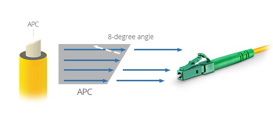
'PC' indicates the fiber optic connector cross-section process, and PC is the most common. APC type was more commonly used in broadcasting and early CATV. The pigtail head uses an angled (8 degrees) end face. The angle is generally not visible, which can improve the quality of television signals. The main reason is that television signals are analog optical modulation, and when the connector coupling surface is perpendicular, the reflected light returns along the original path. Because of the uneven refractive index distribution of the optical fiber, the reflected light will return to the coupling surface. Although the energy is very small at this point, analog signals cannot completely eliminate noise, so it's equivalent to superimposing a weak signal with a time delay onto the original clear signal. This manifests as ghosting in the image. An angled pigtail tip prevents the reflected light from returning along its original path. This problem generally does not exist with digital signals.
There is also a 'UPC' process, which has lower attenuation than PC. Equipment with special requirements typically uses FC/UPC flanges. Foreign manufacturers use FC/UPC for internal patch cords in their ODF racks to improve the performance of the ODF equipment itself.

How to test if a fiber optic patch cord is qualified?
First, use a light pen to check if the patch cord transmits light, ensuring the fiber is not broken. Measure the specifications: Typical telecom-grade specifications are: insertion loss less than 0.3dB and return loss greater than 45dB.
Fiber optic patch cord performance testing includes:
1. Optical performance testing, including return loss/insertion loss testing.
2. End-face geometry testing, including parameters such as radius of curvature, vertex offset, and fiber height.
3. Fiber end-face scratch detection, using a video fiber optic magnifying glass. This instrument provides the clearest image; it integrates 400x, 200x, and 80x magnification lenses for clear and convenient observation of the fiber end-face and ferrule end-face. Automatic inspection can also be performed using relevant software.
4. Fiber tensile strength testing, which tests the tensile force the fiber optic connector can withstand.
5. Ambient temperature testing: This involves testing the performance indicators of the fiber optic connectors under different ambient temperatures.
As a professional fiber optic manufacturer, HUALUE provides high-quality fiber patch cords engineered for low insertion loss, high reliability, and customized configurations. With strict quality control and advanced production capabilities, HUALUE supports global customers in building reliable fiber optic networks for telecom, enterprise, and data center applications.









